Divergence Meter Battery Mod

The divergence meter I built can be powered by an internal 9V battery. However, a regular 9V battery doesn’t last very long (between 10 and 45 minutes). LiPo 9V batteries last much longer – over 3 hours, though they aren’t really 9V as they are actually two regular LiPo batteries in series – so the actual voltage is at most 8V, dropping to 6V just before the power runs out.

However, that still means that you have to open the clock up to change the battery when it is out of power. A better alternative would be to include a power-sharing charger inside the case, so that the LiPo will charge up when the clock is plugged back into the power. A quick(ish) search of the internet turned up this 9V LiPo charger module, which is small enough to fit inside the case along with the battery. So that gave me the charger, but I needed to add the load-sharing part. A load-sharing charger will use some of the input power (input from the wall adapter) to charge up the battery, while the clock runs off the rest. It also needs to disconnect the battery from the clock as long as the clock is plugged in to the wall adapter, but instantly connect the battery to the clock as soon as it is unplugged from the wall adapter. This is actually pretty easy, and my circuit is basically the one described here.

Here is the basic circuit:
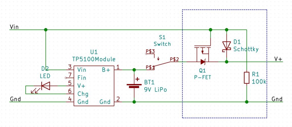
Load Sharing Charger

The load-sharing part is inside the dashed box. Here is what my implementation of this looks like. I used a surface-mount MOSFET, because I happened to have one already:
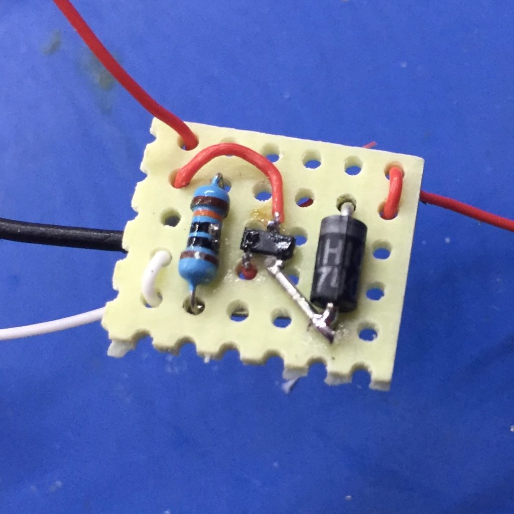
Load Sharer

This works as follows:

  1. As long as there is power on Vin, the P-channel MOSFET (Q1) will be turned off, preventing any power from being discharged from the battery and also preventing any power from Vin being directly applied to the positive terminal of the battery. Power from Vin will flow to V+ through the Schottky diode (D1).
  2. While there is power on Vin, the TP5100 module will also be able to charge the battery, if necessary.
  3. As soon as power is removed from Vin, the 100K resistor (R1) will pull Vin to ground, which will turn on the MOSFET allowing current to flow from the battery to V+.
  4. This is why the Schottky diode (D1) is needed. It stops the gate of the MOSFET being pulled high again by the battery, which would turn it off, etc. The only reason that D1 is a Schottky diode, is to minimize the voltage drop from Vin to V+.
  5. The LED (D2) shows when the battery is being charged.

I checked it all out before stuffing it into the case:
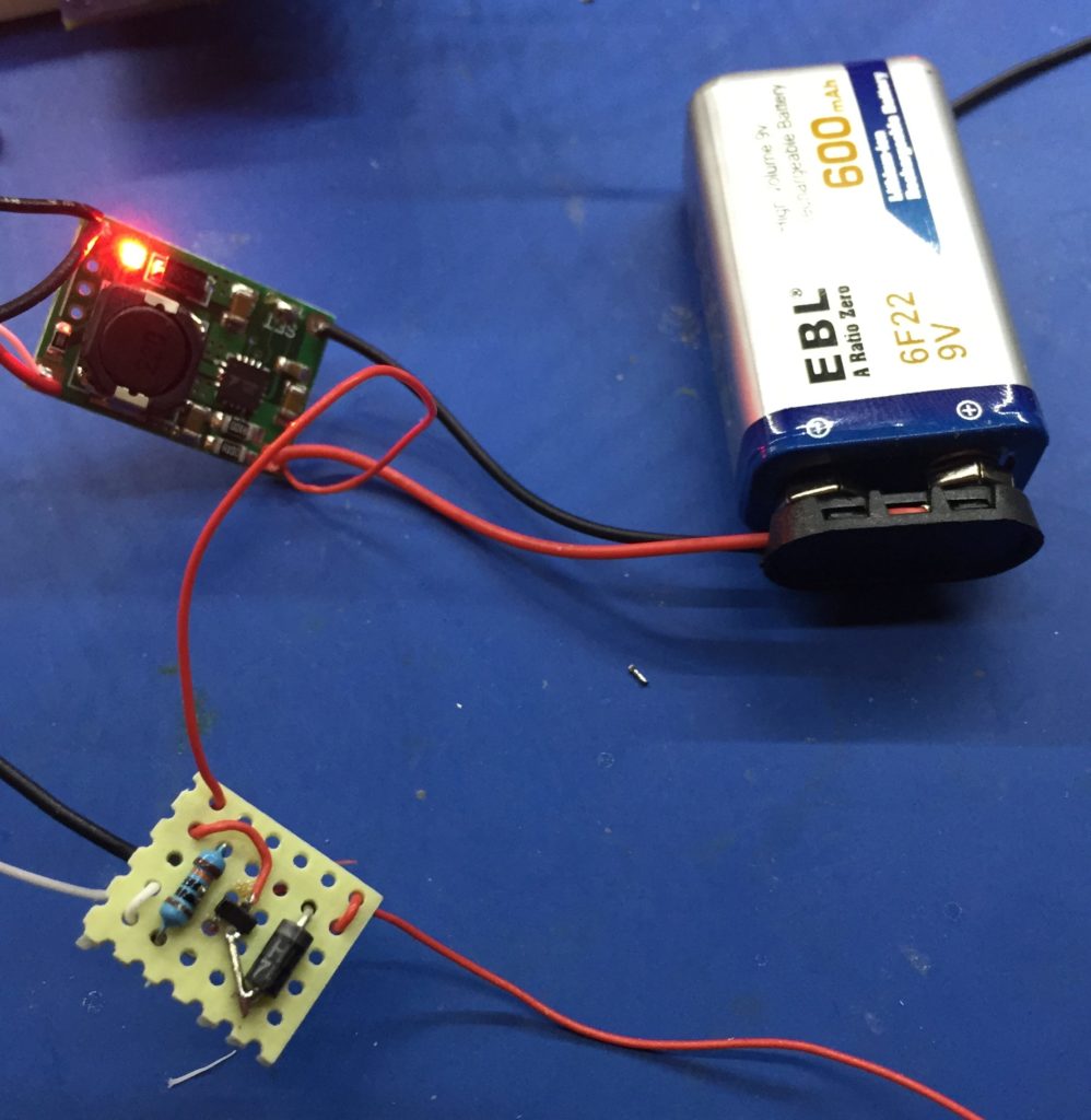
Load Sharing Charger

To integrate this with the clock, you have to cut the track from the Vin pin on the barrel connector (power in), then wire that to the Vin connector on the battery charger. Then wire V+ from the load-sharing board to the other side of the track that you cut – just find an easy place on the board to do that.

To re-use the existing switch, remove the optional diode (if you installed it) and just wire the switch up as shown in the circuit diagram above.

Finally, if you choose to use the charging indicator LED, you will have to drill a hole in the case somewhere to install it.

Here it is in the case:
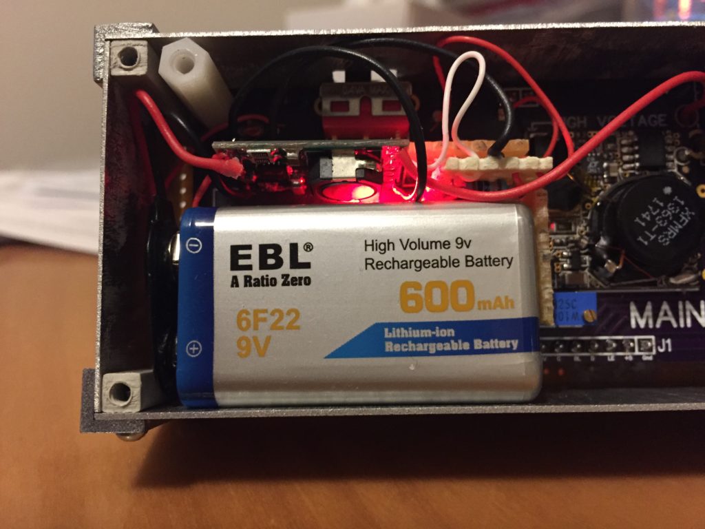
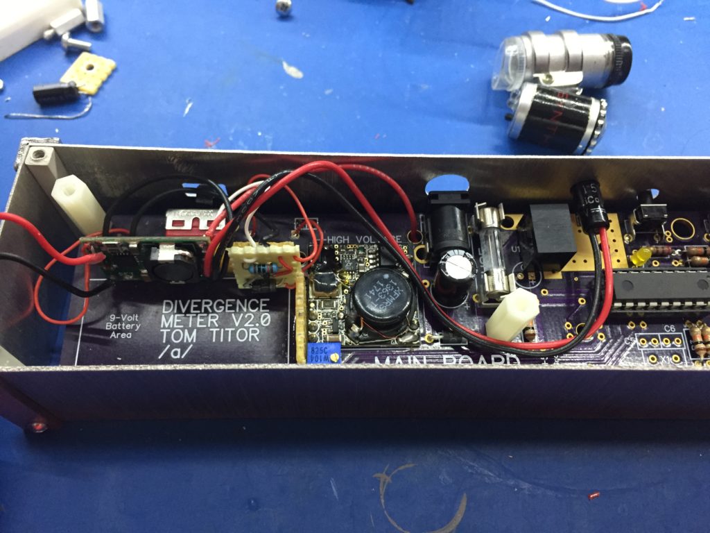
Charger in the Case
View Showing LED Placement

I took a time-lapse video of the clock running off battery. As you can see, it lasts a little over three hours:
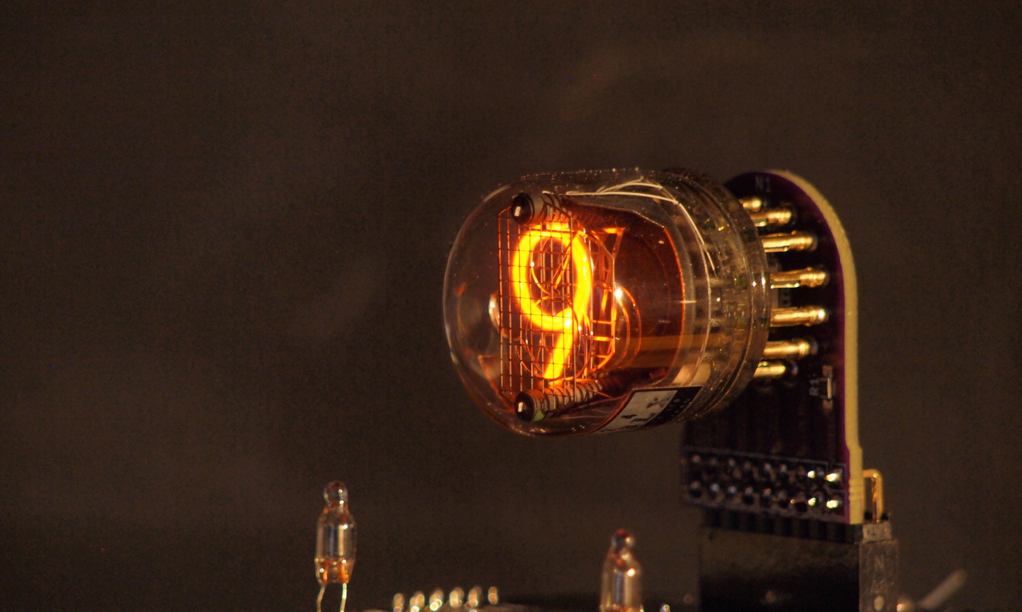
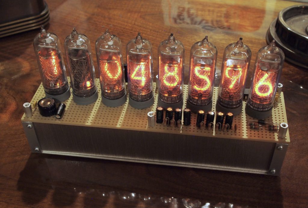
Complete Divergence Meter

I’ve been building a Divergence Meter, as featured in Steins;Gate, using Tom Titor’s excellent design.

Perfboard

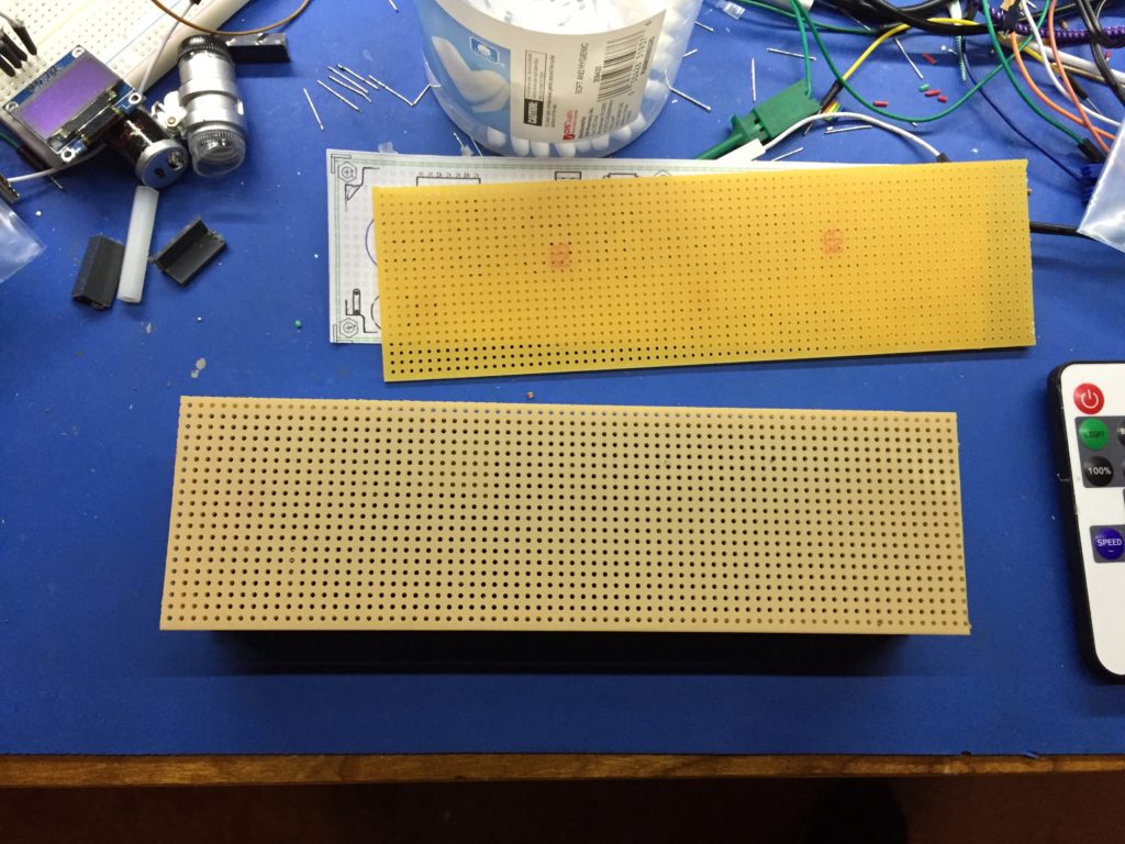
If you’ve read any of my other posts about this project, you’ll know that I hit some obstacles. First I blew up the HV power supply and the PIC chip, then the perfboard I had, had logos printed on both sides. Well I replaced both the power supply and the PIC chip. As for the perfboard, I couldn’t find any that was the right size, the right color and logo-free. In the end I followed a suggestion and spray-painted it. Here’s a before and after shot:

Before and after spray painting

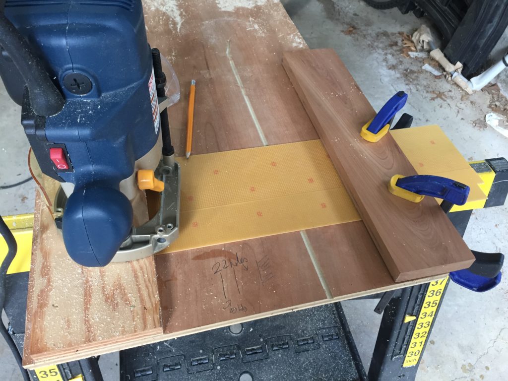
That particular piece wasn’t cut very well, so I used it for practice. To cut the perfboard, I used a technique recommended by a carpenter friend. If you use a saw it is hard to get a clean edge, so I used a router instead. Here is the setup I used:

Router Jig

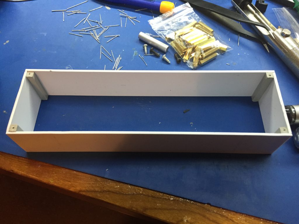
Case

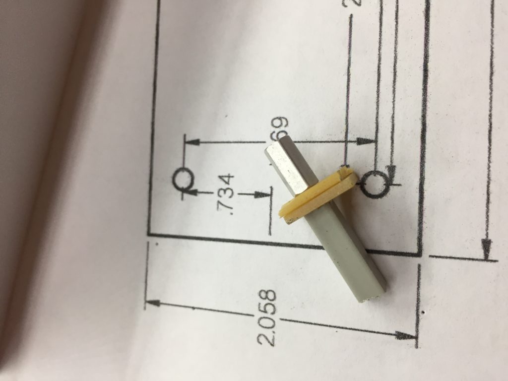
And that is pretty much where I stopped for a while – I still hadn’t figured out how I was going to build the case. I played around with prototypes made out styrene sheet, and while I was doing that I realized that the hex standoffs used to hold the top to the case screwed easily into the plastruct rod I was using to brace the corners – it has a round hollow core:

Plastruct rod test 1

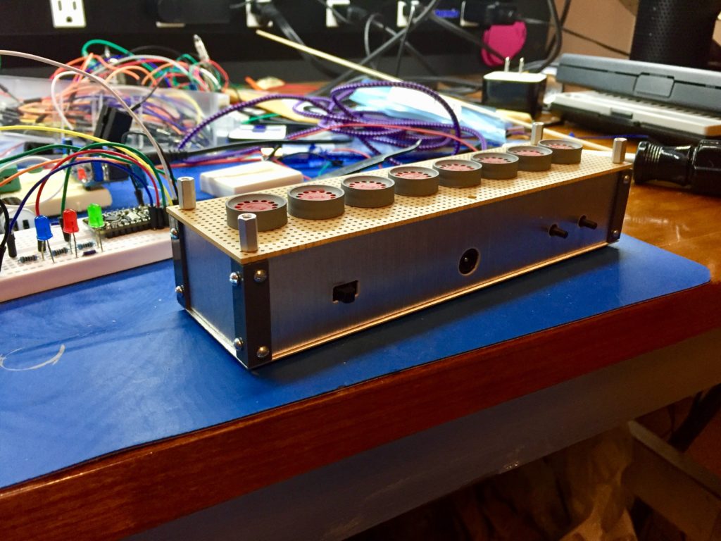
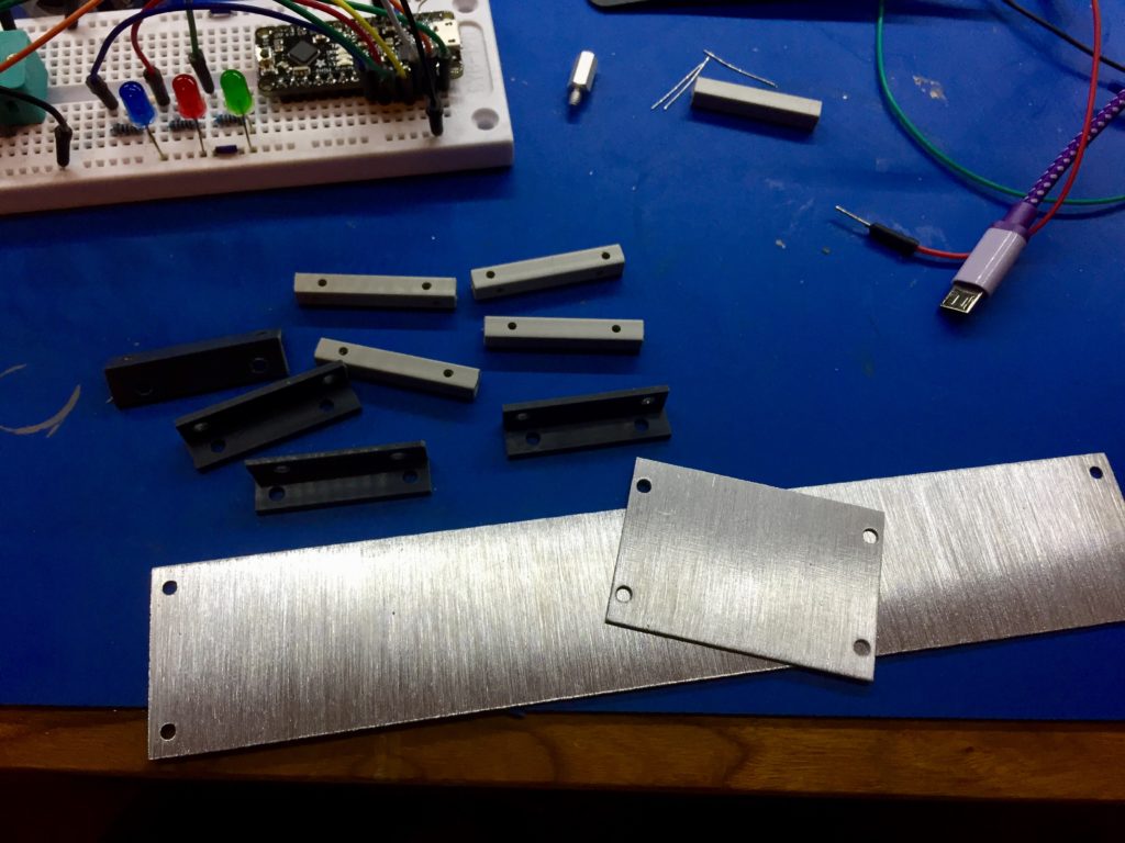
And then it suddenly occurred to me that I could drill pilot holes in the rod, and use self-tapping screws to fix the sides of the case to the rod. I tested it on some aluminum sheet I had, and it worked really well. So now all I had to do was CAD it up and get it made by Big Blue Saw. Here is a shot of the end result:

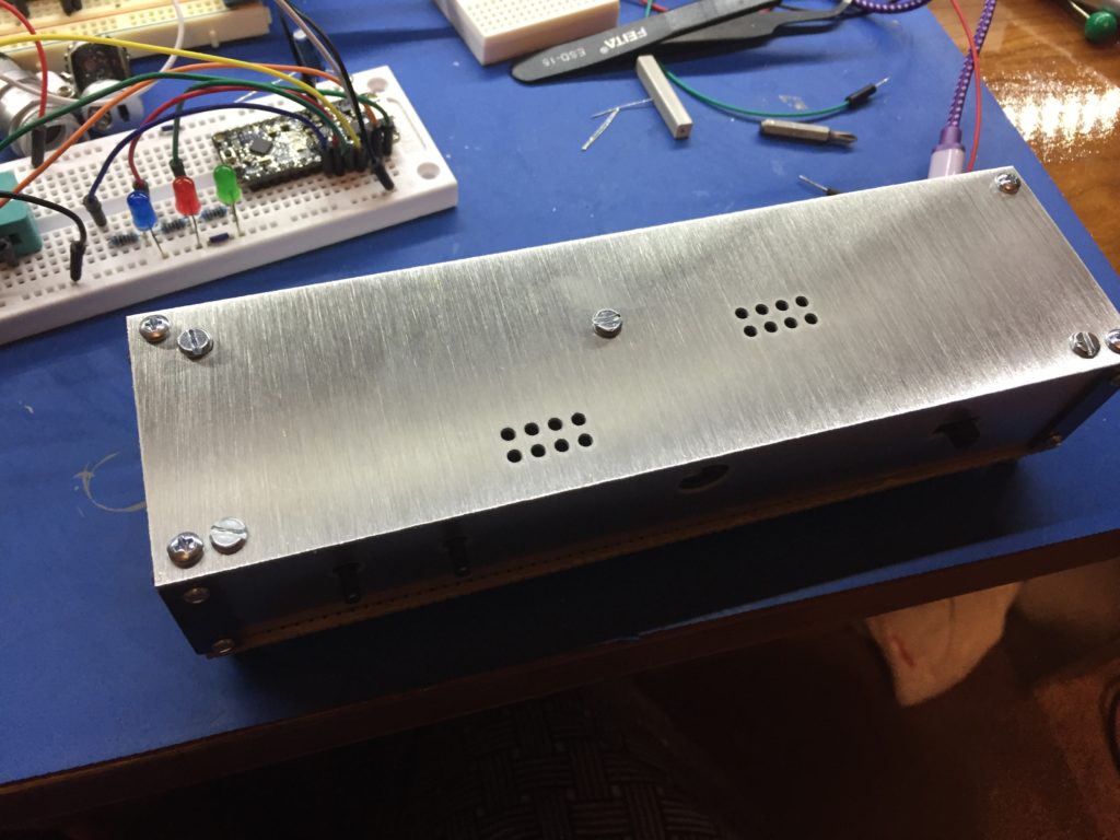
Case from the back
Drilled plastruct and some of the case parts.

I had also decided that the PCBs inside the case needed some good support, so I used 11/16″ plastic standoffs to mount the main board to the case. It needs to be this length to accommodate a 9V battery. By my calculations that meant I also had to increase the height of the case slightly, so I did.

Construction

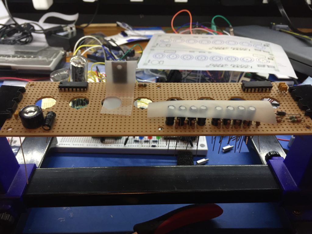
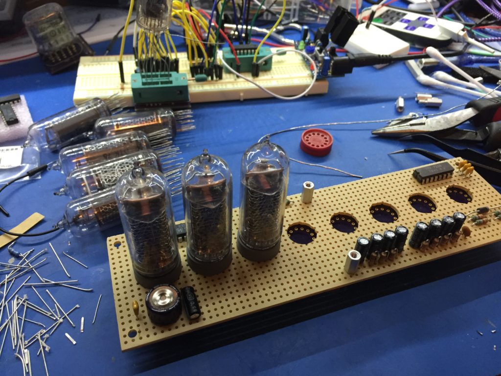
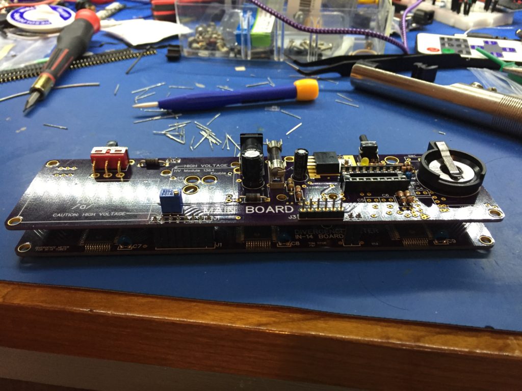
Now I knew everything would go together I could get on with the rest of the construction. Here are a few progress shots:

Gluing the dummy components
Soldering in the tubes

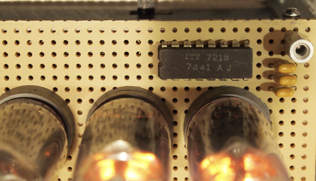
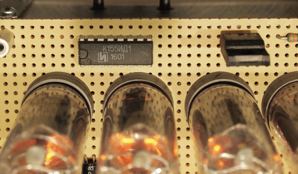
For some extra veracity, I used a busted 7441 chip and a busted К155ИД1 chip for the dummy ICs:

ITT 7441 dummy IC
К155ИД1 dummy IC

I discovered that the gloopy super glue I was using (aka CA Adhesive), really didn’t want to cure. Tom had mentioned that it would be useful to have some accelerant, and I guess it is. Googling CA glue accelerator shows it is just a mild alkaline solution that neutralizes the acid used in the glue, to slow down curing. I found this article about how to make your own, so I did and it worked great.

Software

The programmer in me couldn’t leave the code alone, so I modified it a little. There are two main changes:

  1. The wordline modes will automatically go on to the next wordline after about 9s, unless a button is pressed.
  2. In clock mode, it will display a random world line twice an hour.

I uploaded the source and a hex file to GitHub.

Finished Clock

Finally, here’s a shot of the finished clock:

World Line Display

Divergence Meter Setbacks

Firstly, I only ordered one push-button instead of two. Annoying, but not a big deal.

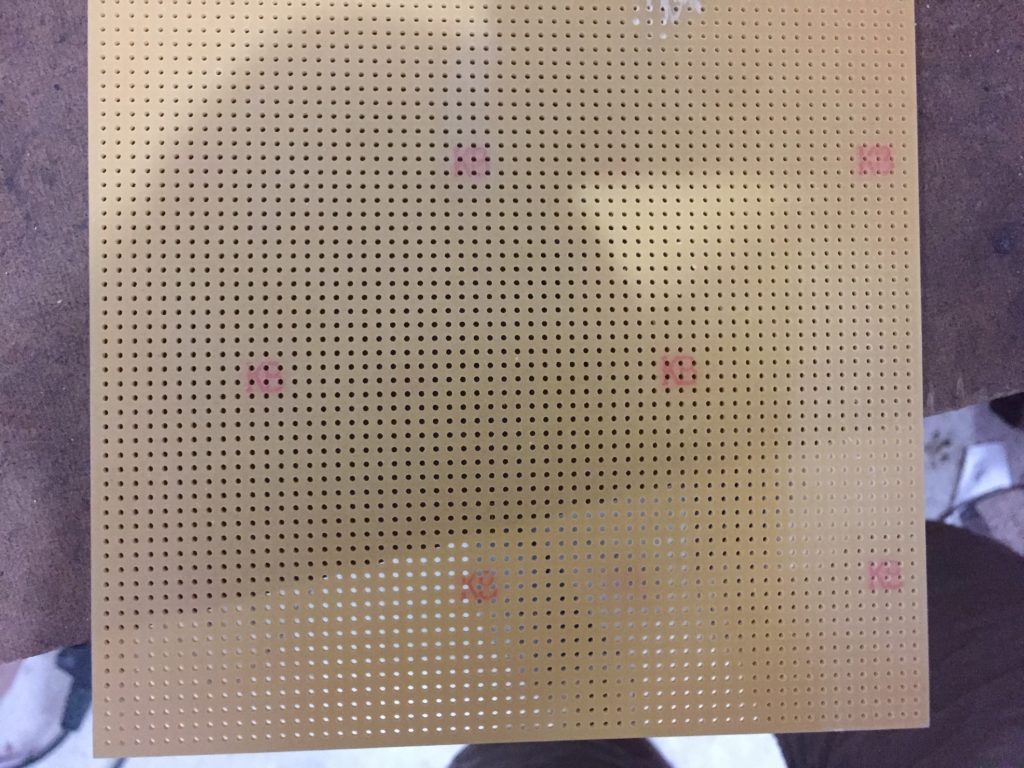
Secondly, the perfboard had logos printed all over it. No chemical would get them off. Sanding didn’t get them off. When I used a dremel, I discovered the pigment went deep into the substrate. I figured that maybe this was just the particular supplier that DigiKey was using, so I ordered some straight from the public BOM on Mouser. It is exactly the same. So I am down $34 on perfboard I can’t use.

Perfboard
Perfboard + Logos

I have ordered yet another perfboard for $23 from DigiKey from a different manufacturer. Hopefully this one won’t be covered in logos. So $57 on perfboard alone. So far!

Thirdly, I missed that the boards on OSH Park need an additional diode near the battery switch. Fortunately I had a suitable Schottky diode lying around.

Fourthly, when I was adjusting the HV it mysteriously stopped working, and the PIC started to get hot. I guess I shorted the HV to the PIC, though I don’t recall doing so. So I am down the HV and the PIC. The HV part is $14. The shipping is $10. So I am now down an extra $60 with little to show for it. Plus I had to unsolder the HV. Fun times!

Since there is little else I can do at this point, I built a prototype case with the styrene sheet. This is so I can test the positioning of the openings on the case before I get some metal ones fabbed.

Anyway, here are the boards, with a gaping hole where the power supply should be 🙁

Divergence Meter

Divergence Meter Kickoff

Its time to actually start building this divergence meter:

Divergence Meter Kickoff

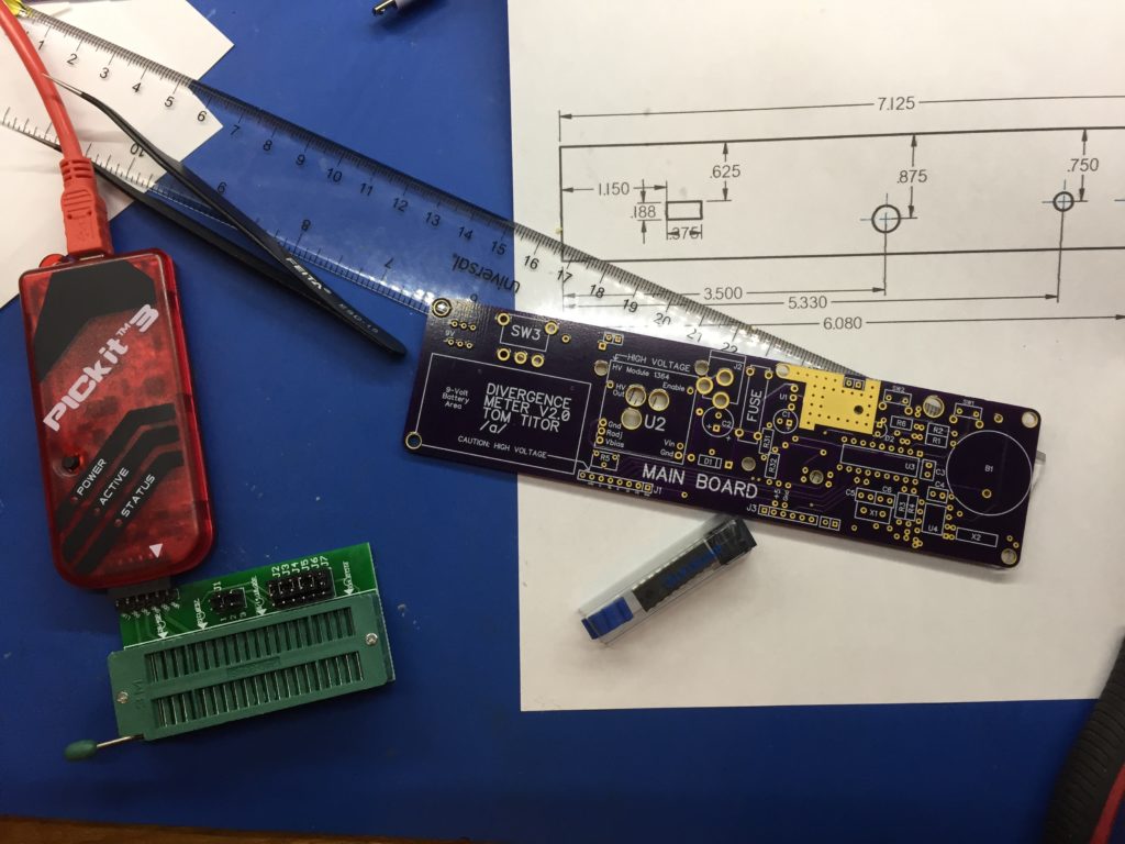
I ordered the parts from Digikey, which have arrived. I chose to program the PIC16F628A myself, by which I mean upload the hex file from Tom Titor. Partly this is because I figure I might modify the program at some point. So I bought a cheap pickit 3 copy off ebay.

I’ve also been re-familiarizing myself with SolidEdge 2D as I would like to get the case pieces fabricated, so I will need an accurate CAD model, and I have used SolidEdge in previous projects.

In addition I have been mulling over how to actually build the case. Ideally I would like to make my own posts with a square cross-section and tap them for screws – I really don’t like the idea of gluing things together – however that is way beyond me at the moment. I also toyed with the idea of using styrene sheets  that are used in modelling. So in the end I bought samples of various materials and practiced gluing things together:

Practice pieces for the case

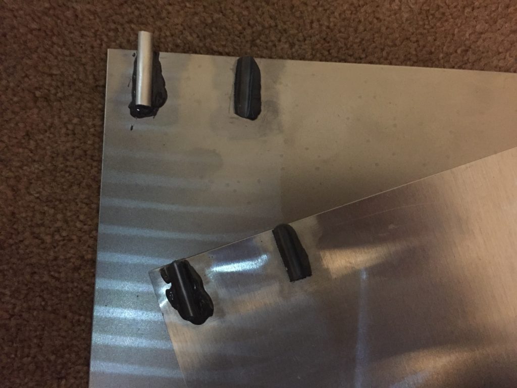
The top sheet is aluminum. The bottom sheet is steel. The left hand blob of glue is JB Kwik, the right hand blob is JB Putty. I glued some aluminum rod to the sheets with an overhang so I could try and pull them off. I roughed up everything with a dremel tool before hand and cleaned it all up with Isopropyl alcohol. In the end I was surprised how strong the bond made by the JB Kwik was, so I am reasonably confident that I can glue standoffs to cut sheets to make the case.

I also glued square rod to the styrene sheets. The bond here was actually pretty good, but they peeled off if I flexed the sheet. When I examined the styrene, it had been softened by the cement. I will probably use the styrene sheets to make some prototypes from my drawings to check that I got all the measurements right.

Now I need to start some soldering.

Divergence Meter

Divergence Meter

I recently acquired some PCBs for building a Divergence Meter as described on Tom Titor’s site. I’ve been meaning to build one of these for a long time.

I struggled for quite a while trying to figure out how to build the case. I didn’t like the idea of using glue as a structural element, and I thought it ought to be possible to source something other than hex standoffs to form the corner posts. I did manage to find a source for square standoffs – though not in small quantities, but that still left the problem of using glue. Ideally I wanted to use actual screws, but that would have meant tapping some small metal rods. I was getting nowhere, so I went to visit my local model shop and chatted with them about various options. I came away with some styrene sheet, some square plastruct rod and some plastruct angle. I figured I could prototype a case and see if anything came to me. I also bought some steel sheet and some aluminum sheet to see how good the glue approach was.

As I messed around with prototypes, I discovered that #4 screws (such as the screw part of the hex standoffs used on the perfboard) screw into the plastruct rod perfectly, so I went to my local hardware store and picked up the smallest self-tapping screws they had – some #2 – 1/4″ screws, drilled pilot holes in the plastruct rod and tried fixing them to some of the metal sheet I had bought. It gripped really well, so I decided that I would CAD up some parts for a case and get them made at Big Blue Saw.

I also decided that I would support the PCBs on plastic hex standoffs, they needed to be well fixed to the case. 11/16″ standoffs work for the main board, with 10mm standoffs between the main board and the display board. For the screws that screw into the bottom of the plastruct rod, I used #4-40X1/8. I have node idea where I bought them – I can’t find them in my ebay, DigiKey or Mouser orders. They need to be short to clear the self-tapping screws.

I have just finished putting together a case using the parts made by Big Blue Saw, and it works great. I had 10 sets made as each set is then a lot cheaper, so I have many left over I currently have two left that I would be willing to sell for $59 + shipping.

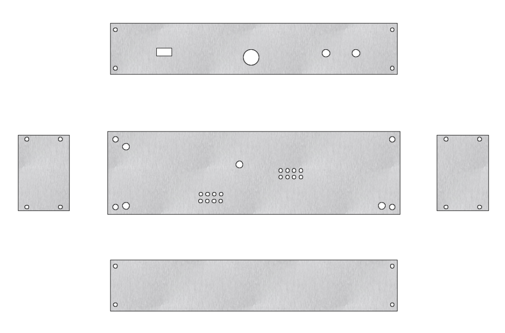
Divergence Meter case design

The following pictures show the case in various stages of construction. This first one shows the plastruct rods and angles. The pilot holes in the rods are 1/16″, the holes in the angle are 7/64″, and not shown – but the holes for the hex standoffs in the perfboard are at least 1/8″.

Drilled plastruct and some of the case parts.

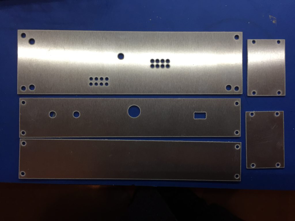
Big Blue Saw offer several finishes. The one below is raw. The edges are very rough, and there are marks left over from the water cutter, so I ordered the rest in basic finish instead.

All the case parts in raw finish
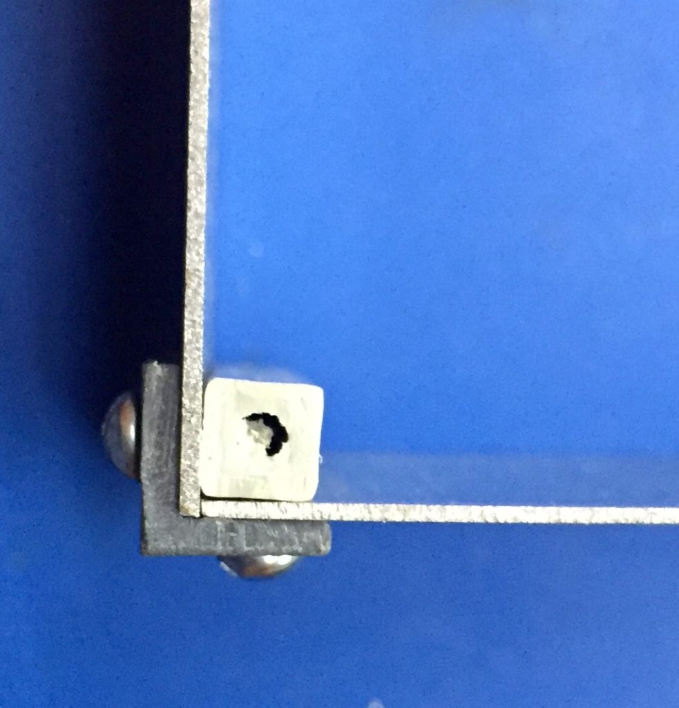
Corner detail, showing how it all fits together

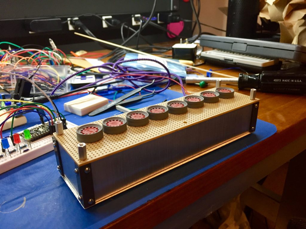
In the photograph below, I have yet to paint the plastruct angle – I was just checking that everything went together.

Front view
Back view
Bottom view

The stencil that Tom provides is slightly different for this case. The holes for the hex standoffs are back where they were with his build #1. In the PDF below I also show cutouts for the tubes with a diameter of 14mm. This is a standard size for things like Forstner bits and it gives you some room for error in drilling these holes!

Perfboard Stencil