This is the fifth post about a nixie clock project that is powered by a vacuum tube power supply, rather than the more common 12V or 5V wall wart.
After part 3, I took a brief detour to talk about the controller hardware, and I had left off talking about the lack of a 5V supply. I had originally hoped to power everything from the mains transformer, but my choice of vacuum tubes made that impossible, because they pulled the 5V and 6V3 supplies up to a high potential, and my circuitry needs to share a 0V rail with the HV supply.
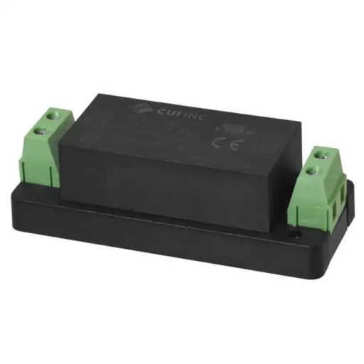
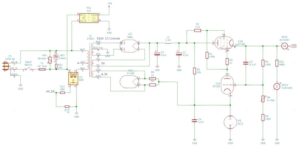
The other aspect of all of this, that I hadn’t managed to resolve, was that I wanted to be able to turn off the HV from the control circuitry. I had mulled over just severing the input the rectifiers (because I wanted to keep the 6V3 winding alive for the 5V DC rail), but now that I couldn’t use that anyway, the problem was solved. I would just use a separate 5V supply and use a SSR (Solid State Relay) to control the mains input to the transformer. I went with a fully enclosed chassis mount 5V supply from CUI.

One final thing I added was a varistor across the input to protect against voltage spikes. One thing I wish I had added, but didn’t, was an inrush current suppressor.
So anyway, this is the final final circuit:

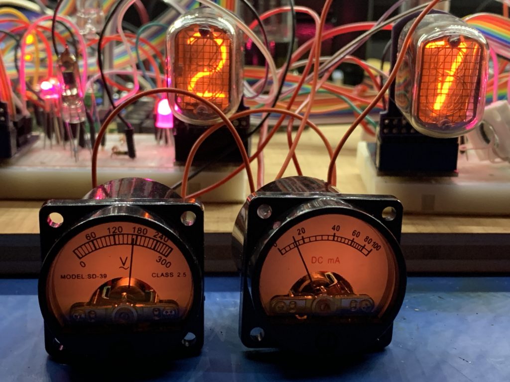
You’ll notice that this circuit includes a voltmeter and an ammeter. I had originally intended to add a voltage/current display using CD13 nixie tubes, which are very small, but I decided this was a step too far. In the end I went for a couple of analog meters because I could put them in the high side, unlike digital meters. I felt that they also matched the aesthetics better than digital meters would. They aren’t just for show. I wanted a simple way of monitoring the voltage and current over time so it would be more obvious if things were starting to drift.

You might notice that the voltmeter is for AC (the ~ symbol under the V). I took one of these apart to see what was inside, and it is just a diode to rectify the voltage, so it would be fine with DC too, but I would have to add a resistor in series to re-calibrate it for DC.
These were the smallest, old-style meters I could find, and they included the internal illumination. I drove the bulbs off the 6V3 circuit, so they are a little dim, but that is OK by me.
